Installing a Physical POD
The following is a detailed, step-by-step recipe for installing a physical POD with multiple physical servers and switches.
If you are new to CORD and would like to get familiar with it, you should start by bringing up a virtual POD on a single physical server.
Overview of a CORD POD
The following is a brief description of a full physical POD.
Physical Configuration
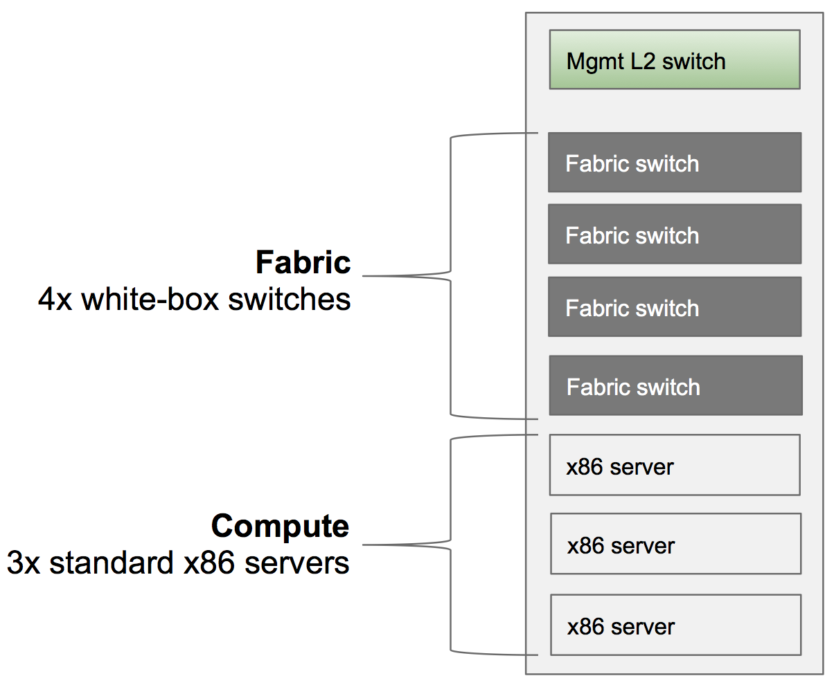
A full POD includes a Top-of-Rack (ToR) management switch, four fabric switches, and three standard x86 servers. The following figure does not show access devices or any upstream connectivity to the metro network; those details are included later in this section.
Logical Configuration: Data Plane Network
The following diagram is a high level logical representation of a typical CORD POD.
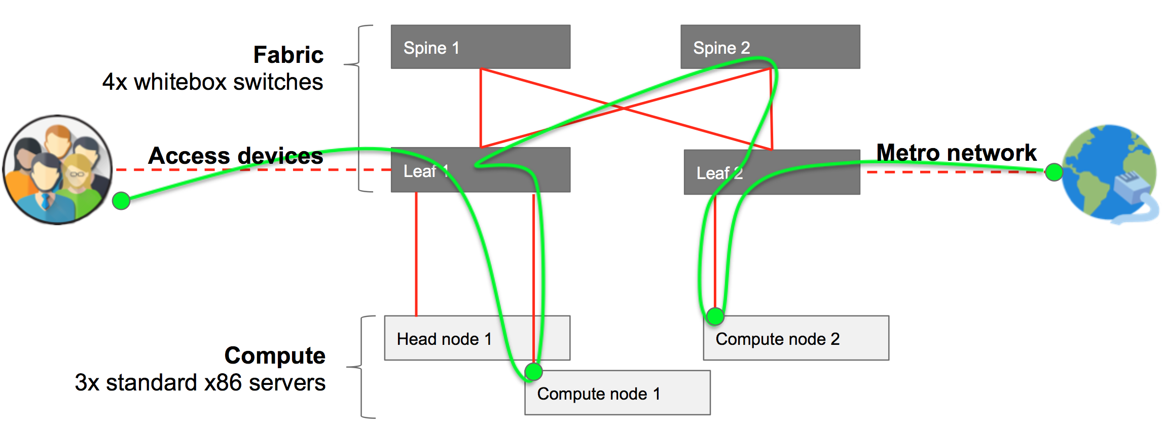
The figure shows 40G data plane connections (red), where end-user traffic goes from the access devices to the metro network (green). User traffic goes through different different leafs, spines and compute nodes, depending on the services needed, and where they are located. The switches form a leaf and spine fabric. The compute nodes and the head node are connected to a port of one of the leaf switches.
Logical Configuration: Control Plane / Management Network
The following diagram shows in blue how the components of the system are connected through the management network.
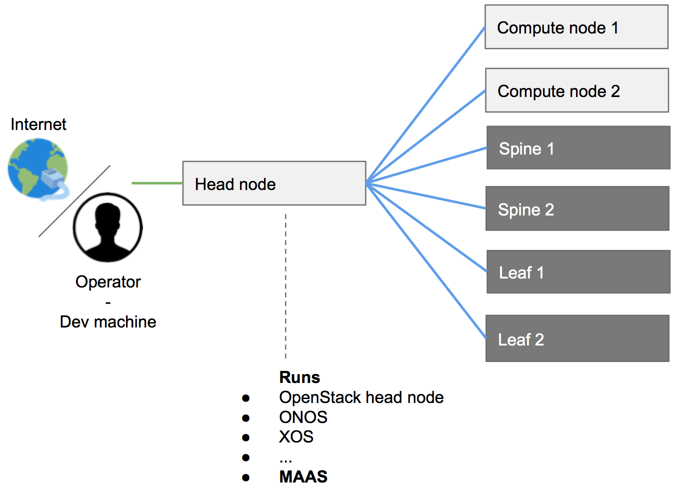
As shown in this figure, the head node is the only server in the POD connected both to Internet and to the other components of the system. The compute nodes and the switches are only connected to the head node, which provides them with all the software needed.
Sample Workflow
It is important to have a general picture of installation workflow before getting into the details. The following is a list of high-level tasks involved in bringing up a CORD POD:
- CORD software is downloaded and built on the dev machine.
- A POD configuration is created by the operator on the dev machine.
- The software is pushed from the dev machine to the head node.
- Compute nodes and fabric switches need to be manually rebooted. The CORD build procedure automatically installs the OS, other software needed and performs the related configurations.
- The software gets automatically deployed from the head node to the compute nodes.
Requirements
While the CORD project is for openness and does not have any interest in sponsoring specific vendors, it provides a reference implementation for both hardware and software to help users in building their PODs. What is reported below is a list of hardware that, in the community experience, has worked well.
Also note that the CORD community will be better able to help you debugging issues if your hardware and software configuration look as much as possible similar to the ones reported in the reference implementation, below.
Bill Of Materials (BOM) / Hardware Requirements
The section provides a list of hardware required to build a full CORD POD.
BOM Summary
| Quantity | Category | Brand | Model | Part Number |
|---|---|---|---|---|
| 3 | Compute | Quanta (QCT) | QuantaGrid D51B-1U | QCT-D51B-1U |
| 4 | Fabric Switch | EdgeCore | AS6712-32X | AS6712-32X |
| 1 | Management Switch (L2 VLAN support) | * | * | * |
| 7 | Cabling (data plane, fiber) | Robofiber | QSFP-40G-03C | QSFP-40G-03C |
| 12 | Cabling (management, copper) | CAT6, 3M | * | * |
Detailed Requirements
1x Development Machine. It can be either a physical machine or a virtual machine, as long as the VM supports nested virtualization. It doesn’t have to be necessarily Linux (used in the rest of the guide, below); in principle anything able to satisfy the hardware and the software requirements. Generic hardware requirements are 2 cores, 4G of memory, 60G of hdd.
3x Physical Servers: one to be used as head node, two to be used as compute nodes.
Suggested Model: OCP Inspired™ QuantaGrid D51B-1U server. Each server is configured with 2x Intel E5-2630 v4 10C 2.2GHz 85W, 64GB of RAM 2133MHz DDR4, 2x 500GB HDD, and a 40 Gig adapter.
Strongly Suggested NIC:
- Intel Ethernet Converged Network Adapters XL710 10/40 GbE PCIe 3.0, x8 Dual port.
- ConnectX®-3 EN Single/Dual-Port 10/40/56GbE Adapters w/ PCI Express 3.0.
NOTE: while the machines mentioned above are generic standard x86 servers, and can be potentially substituted with any other machine, it’s quite important to stick with either one of the network card suggested. CORD scripts will look for either an
i40eor amlx4_endriver, used by the two cards. To use other cards additional operations will need to be done. Please, see Network Settings for more information.
4x Fabric Switches
- Suggested Model: OCP Accepted™ Accton 6712 switch. Each switch is configured with 32x40GE ports; produced by EdgeCore and HP.
7x Fiber Cables with QSFP+ (Intel compatible) or 7 DAC QSFP+ (Intel compatible) cables
- Suggested Model: Robofiber QSFP-40G-03C QSFP+ 40G direct attach passive copper cable, 3m length - S/N: QSFP-40G-03C.
1x 1G L2 copper management switch supporting VLANs or 2x 1G L2 copper management switches
Connectivity Requirements
The dev machine and the head node have to download software from different Internet sources, so they currently need unfettered Internet access. (In the future, only the dev machine, and not the head node, will require Internet connectivity.) Sometimes firewalls, proxies, and software that prevents to access local DNSs generate issues and should be avoided.
Cabling a POD
This section describes how the hardware components should be interconnected to form a fully functional CORD POD.
Management / Control Plane Network
The management network is divided in two broadcast domains: one connecting the POD to the Internet and giving access to the deployer (called "external" and shown in green in the figure below), and one connecting the servers and switches inside the POD (called "internal" or "management" and shown in blue). The figure also shows data plane connections in red (as described in the next paragraph).
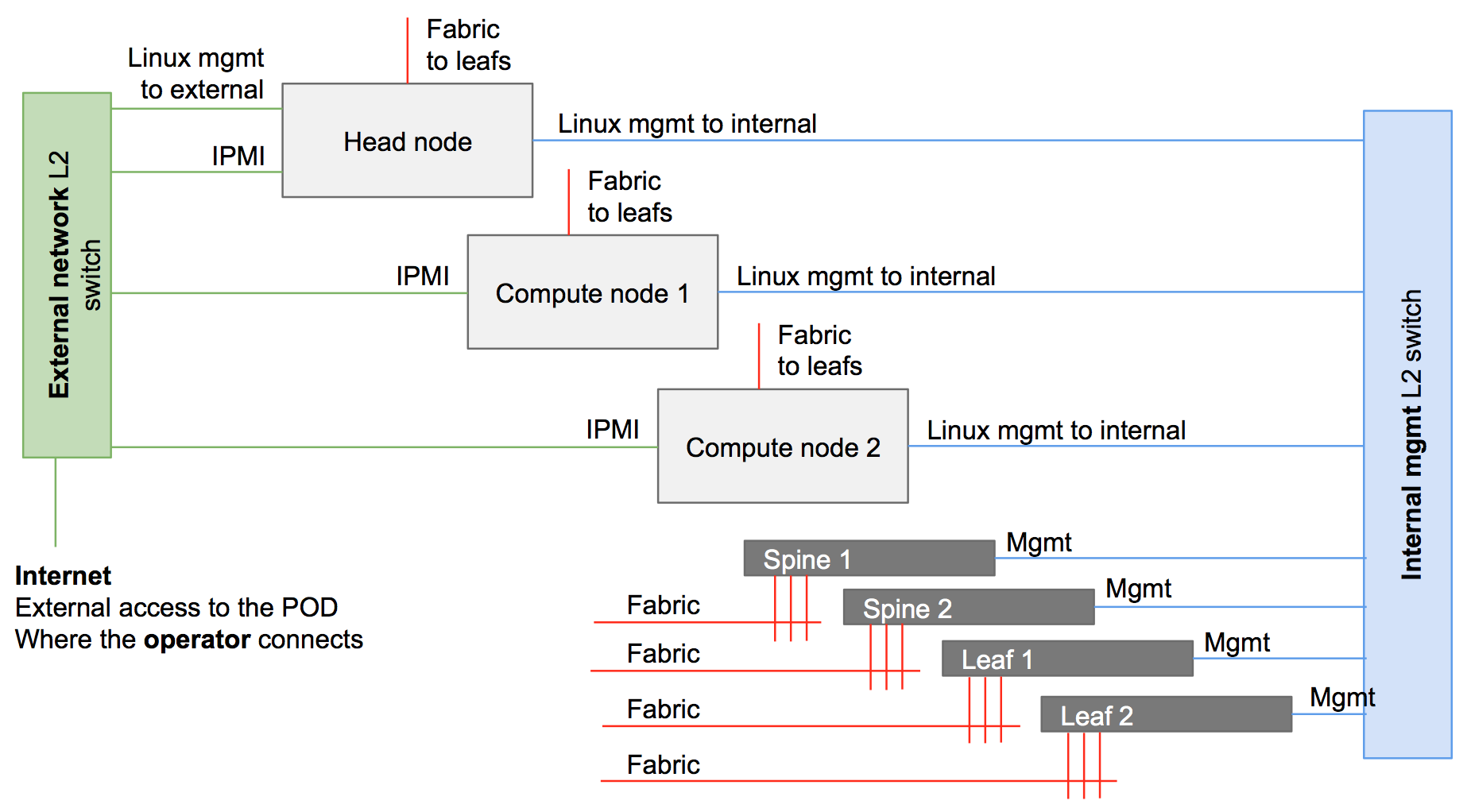
The external and the management networks can be separated either using two different switches, or the same physical switch and by using VLANs.
NOTE: Head node IPMI connectivity is optional.
NOTE: IPMI ports do not have to be necessarily connected to the external network. The requirement is that compute node IPMI interfaces need to be reachable from the head node. This is possible also through the internal / management network.
NOTE: Vendors often allow a shared management port to provide IPMI functionalities. One of the NICs used for system management (e.g., eth0) can be shared, to be used at the same time also as IPMI port.
External Network
The external network allows POD servers to be reached from the Internet. This would likely not be supported in a production system, but is useful in development and evaluation settings, for example, making it easy to directly start/stop/reboot the head and the compute nodes. Moreover, using CORD automated scripts and tools for Jenkins pipeline requires Jenkins direct access to these interfaces. This is why IPMI/BMC interfaces of the nodes are also connected to the external network. In summary, following is the list of equipment/interfaces usually connected to the external network:
- Internet
- Dev machine
- Head node - 1x 1G interface (following defined as external)
- Head node - 1x IPMI/BMC interface (optional)
- Compute node 1 - 1x IPMI/BMC interface (optional, but recommended)
- Compute node 2 - 1x IPMI/BMC interface (optional, but recommended)
Internal Network
The internal/management network is separate from the external one. It has the goal to connect the head node to the rest of the system components (compute nodes and fabric switches). For a typical POD, the internal network includes:
- Head node - 1x 1G interface (following defined as management)
- Compute node 1 - 1x 1G interface
- Compute node 2 - 1x 1G interface
- Fabric 1 - management interface
- Fabric 2 - management interface
- Fabric 3 - management interface
- Fabric 4 - management interface
User / Data Plane Network
The data plane network (represented in red in the figure) carries user traffic (in green), from the access devices to the point the POD connects to the metro network.
The fabric switches are assembled to form a leaf and spine topology. A typical full POD has two leafs and two spines. Currently, this is a pure 40G network. While spines are not connected together, each leaf is connected to both spines. In summary, the following are the devices connecting to the leaf switches:
- Head node - 1x 40G interface
- Compute node 1 - 1x 40G interface
- Compute node 2 - 1x 40G interface
- Access devices - 1 or more 40G interfaces
- Metro devices - 1 or more 40G interfaces
Best Practices
The community follows a set of best practices to better be able to remotely debug issues, for example via mailing-lists. The following is not mandatory, but is strongly suggested:
Leaf nodes are connected to the spines nodes starting at the highest port number on the leaf.
For a given leaf node, its connections to the spine nodes terminate on the same port number on each spine.
Leaf n connections to spine nodes terminate at port n on each spine node.
Leaf-spine switches are connected into the management TOR starting from the highest port number.
Compute node n connects to the internal (management) network switch on port n.
Compute node n connects to its leaf at port n.
The head node connects to the internal (management) network using the lowest 1G management interface.
The head node connects to the external network using its highest 1G management interface.
All servers connect to the leafs using the lowest fabric (40G NIC) interface.
Software Environment Requirements
Only the dev machine and the head node need to be prepped for installation. The other machines will be fully provisioned by CORD itself.
Development Machine
It should run either Ubuntu 16.04 LTS (recommended) or Ubuntu 14.04 LTS. See Configuring your Development Environment for more details.
This documentation assumes that you checked out the CORD source tree into
~/cord.
Head Node
It should run Ubuntu 14.04 LTS. Then, configure the following.
Create a User with "sudoer" permissions (no password)
sudo adduser cord && \
sudo adduser cord sudo && \
echo 'cord ALL=(ALL) NOPASSWD:ALL' | sudo tee --append /etc/sudoers.d/90-cloud-init-users
Compute Nodes
The CORD build process installs the compute nodes. The only thing to be configured are the BIOS settings, so that they can PXE boot from the head node through the internal (management) network. In doing this, make sure that:
The network card connected to the internal / management network is configured with DHCP (no static IPs).
The IPMI (sometime called BMC) interface is configured with a statically assigned IP, reachable from the head node. It’s strongly suggested to have them deterministically assigned, so you will be able to control your node as you like.
Their boot sequence has (a) the network card connected to the internal / management network as the first boot device; and (b) the primary hard drive as second boot device.
NOTE: Some users prefer to connect as well the IPMI interfaces of the compute nodes to the external network, so they can have control on them also from outside the POD. This way the head node will be able to control them anyway.
Fabric Switches: ONIE
The ONIE installer should be already installed on the switch and set to boot in installation mode. This is usually the default for new switches sold without an Operating System. It might not be the case instead if switches have already an Operating System installed. In this case rebooting the switch in ONIE installation mode depends by different factors, such the version of the OS installed and the specific model of the switch.
Prepare POD Configuration
Each CORD POD deployment requires a POD configuration file that describes how the system should be configured, including what IP addresses should be used for the external and the internal networks, what users the system should run during the automated installation, and much more.
POD configuration files are YAML files with extension .yml, contained in the
/cord/build/podconfig directory in the dev VM. You can either create a new
file with your favorite editor or copy-and-edit an existing file. The
rcord-physical-example.yml
configuration file is there for this purpose. All parameters have a
description. Optional lines have been commented out, but can be used as needed.
More information about how the network configuration for the POD can be customized can be found in Network Settings.
A full set of all possible build system variables can be found in the Build System Variable Glossary.
Once the POD config YAML file has been created, the composite configuration file should be generated with the following command.
cd ~/cord/build && \
make PODCONFIG={YOUR_PODCONFIG_FILE.yml} config
The process generates a set of files in ~/cord/build/genconfig
NOTE: Before the configuration process the
~/cord/build/genconfigdirectory contains a README.md file only.
Head Node Deployment
Head node deployment works as follows:
- Makes the head node a MAAS server from which the other POD elements (fabric switches and compute nodes) can PXE boot (both to load their OS and to be configured).
- Installs and configures the containers needed to configure other nodes of the network.
- Installs and configures OpenStack.
- Provisions XOS, which provides service provisioning and orchestration for the CORD POD.
This step is started with the following command:
cd ~/cord/build && \
make build
NOTE: Be patient: this step can take an hour to complete.
WARNING: This command sometimes fails for various reasons. Simply re-running the command often solves the problem. If the command fails it’s better to start from a clean head node.
This step is complete when the command successfully runs.
MAAS
As previously mentioned, once the deployment is complete the head node becomes a MAAS region and rack controller, basically acting as a PXE server and serving images through the management network to compute nodes and fabric switches connected to it.
The Web UI for MaaS can be viewed by browsing to the head node, using a URL of
the from http://head-node-ip-address/MAAS.
To login to the web page, use cord as the username. If you have set a
password in the deployment configuration password use that, otherwise the
password used can be found in your build directory under
<base>/build/maas/passwords/maas_user.txt.
After the deployment process finishes, MAAS initiates the download of an Ubuntu
14.04 boot image that will be used to boot the other POD devices. This download
can take some time and the process cannot continue until the download is
complete. The status of the download can be verified through the UI by visiting
the URL http://head-node-ip-address/MAAS/images/, or via the command line
from head node via the following command:
APIKEY=$(sudo maas-region-admin apikey --user=cord) && \
maas login cord http://localhost/MAAS/api/1.0 "$APIKEY" && \
maas cord boot-resources read | jq 'map(select(.type != "Synced"))'
If the output of of the above commands is not an empty list ([]) then the images have not yet been completely downloaded. Depending on your network speed, this could take several minutes. Please wait and then attempt the last command again, until the returned list is empty.
When the list is empty you can proceed.
Compute Node and Fabric Switch Deployment
The section describes how to provision and configure software on POD compute nodes and fabric switches.
General Workflow
Once it has been verified that the Ubuntu boot image has been downloaded, the compute nodes and the fabric switches may be PXE booted.
Compute nodes and switches should be simply rebooted. The head node (through MaaS) will act as DHCP and PXE server. It will install the OSs and will make sure they are correctly configured.
At the end of the process, the compute and switch elements should be visible through the CORD CLI utilities and MAAS.
WARNING: make sure your computes nodes and fabric switches are configured as prescribed in the Software Environment Requirements section.
Important Commands: cord harvest and cord prov
Two important commands are available to debug and check the status of the provisioning. They can be used from the head node CLI.
cord harvest: Tracks the nodes harvesting process. Nodes and switches should appear here, as soon as they get an IP and are recognized by MaaS. To see if your devices have been recognized, use the following command:
cord harvest list
cord prov: Tracks the provisioning process, meaning the configuration process that happen soon after the OS has been installed on your devices. To see the provisioning status of your devices, use the following command:
cord prov list
The following status values are defined for the provisioning status:
- Pending: The request has been accepted by the provisioner but not yet started
- Processing: The request is being processed and the node is being provisioned
- Complete: The provisioning has been completed successfully
- Error: The provisioning has failed and the message will be populated with the exit message from provisioning.
Logs of the post deployment provisioning can be found in
/etc/maas/ansible/logs on the head node.
For a given node, the provisioning re-starts automatically if the related entry gets manually removed. This can be done with the following command:
cord prov delete node_name
Static IP Assignment
If you want to assign a specific IP to either a compute node or a fabric
switch, it should be done before booting the device. This is achieved through a
configuration file: /etc/dhcp/dhcpd.reservations.
To help you, a sample file is available: /etc/dhcp/dhcpd.reservations.sample.
For each host you want to statically assign an IP, use this syntax:
host <name-of-your choice> {
    hardware ethernet <host-mac-address>;
    fixed-address  <desired-ip>;
    }
Compute Nodes
The compute node provisioning process installs the servers as OpenStack compute nodes.
The compute node will boot, register with MaaS, and then restart (eventually multiple times).
Compute nodes are given a random hostname, in the "Canonical way", of
an adjective and a noun (e.g., popular-feast.cord.lab).
The name will be different for every deployment.
After this is complete, an entry for each node will be visible:
From the MaaS UI, at
http://head-node-ip-address/MAAS/#/nodesFrom the OpenStack CLI on the head node, using the command
source /opt/cord_profile/admin-openrc.sh && \
nova hypervisor-list
- From CORD head node CLI, using the
cord harvestcommand
In MaaS, the new node will be initially in a New state. As the machines boot, they should automatically transition from New through the states Commissioned, Acquired and Deployed.
Once the node is in the Deployed state, it will be provisioned for use in a CORD POD by the automated execution of an Ansible playbook.
The post deployment provisioning of the compute nodes can be queried using the
cord prov command.
After a correct provisioning you should see something similar to:
cord prov list
ID                                         NAME                   MAC                IP          STATUS      MESSAGE
node-c22534a2-bd0f-11e6-a36d-2c600ce3c239  steel-ghost.cord.lab   2c:60:0c:cb:00:3c  10.6.0.107  Complete
node-c238ea9c-bd0f-11e6-8206-2c600ce3c239  feline-shirt.cord.lab  2c:60:0c:e3:c4:2e  10.6.0.108  Complete
Once the post deployment provisioning on the compute node is complete, this task is complete.
Fabric Switches
Similar to the compute nodes, the fabric switches will boot, register with MaaS, and then restart (eventually multiple times).
If a name hasn’t been assigned to the switches (see the static IP assignment
section above), usually switches have a name in the form UKN-XXXXXX.
When the fabric switches get an IP and go through the harvesting process, they
should be visible in MaaS, under the devices tab
(http://head-node-ip-address/MAAS/#/devices).
As with the compute nodes, following the harvest process, the provisioning will happen. After a correct provisioning you should see something similar to:
cord prov list
ID                                         NAME                    MAC                IP          STATUS      MESSAGE
cc:37:ab:7c:b7:4c                          UKN-ABCD                cc:37:ab:7c:b7:4c  10.6.0.23   Complete
cc:37:ab:7c:ba:58                          UKN-EFGH                cc:37:ab:7c:ba:58  10.6.0.20   Complete
cc:37:ab:7c:bd:e6                          UKN-ILMN                cc:37:ab:7c:bd:e6  10.6.0.52   Complete
cc:37:ab:7c:bf:6c                          UKN-OPQR                cc:37:ab:7c:bf:6c  10.6.0.22   Complete
NOTE:
cord prov listoutput for compute nodes is not shown here for simplicity.
Once the post deployment provisioning on the fabric switches is complete, the task is complete.
Access to CORD Services
Your POD is now installed. You can now try to access the basic services as described below.
ONOS (Underlay)
A dedicated ONOS instance is installed on the head node to control the underlay
infrastructure (the fabric). You can access it with password rocks:
From the head node CLI:
ssh -p 8101 onos@onos-fabricUsing the ONOS UI, at:
http://<head-node-ip>/fabric
ONOS (Overlay)
A dedicated ONOS instance is installed on the head node to control the overlay
infrastructure (tenant networks). You can access it with password rocks:
From the head node CLI:
ssh -p 8102 onos@onos-cordUsing the ONOS UI, at:
http://<head-node-ip>/vtn
OpenStack
From the head node CLI
$ sudo lxc list
lists the set of LXC containers running the various OpenStack-related services. These containers can be entered as follows:
$ ssh ubuntu@<container-name>
XOS UI
XOS is the cloud orchestrator that controls the entire POD. It allows you to define new service and service dependencies. You can access XOS at:
- Using the XOS GUI at
http://<head-node-ip>/xos - The username is
xosadmin@opencord.organd the auto-generated password can be found in/opt/credentials/xosadmin@opencord.orgon the head node